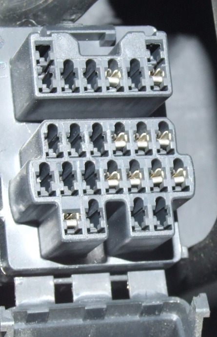
This is the diagnostic box on my '97 Freda 2.5 TurboDiesel.It's sad to see that there are limitations to the information you can get from it, but below is the page prepared by John Wood giving clear instructions for the Mazda 626 -note that the box is shown upside down to the way it's fitted in the Bongo: Bongo owners have to think outside the box.
Obviously neither John nor myself can be responsible for anyone who destroys either themselves, their car or anything else for following these instructions.
The
Diagnostic Connector
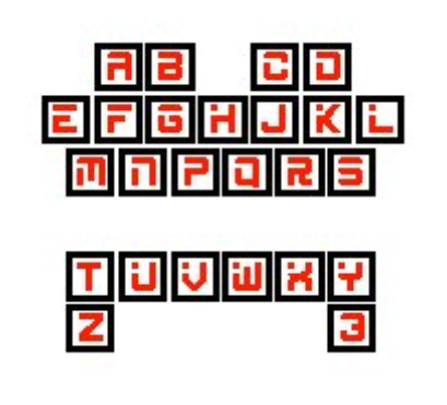
Pin Name (see above)
|
Pin Name
|
Function
|
A
|
FEN
|
Trouble
code output (engine control computer)
|
B
|
MEN
|
Switch
monitor output (engine control computer)
|
C
|
TEN
|
Diagnostic-mode
input (engine control computer)
|
D
|
+B
|
Switched
battery voltage
|
E
|
GND
|
Ground
|
F
|
FAT
|
Trouble
code output (automatic transmission control computer)
|
G
|
FBS
|
Trouble
code output (anti-lock brakes (ABS) control computer)
|
H
|
FAC
|
Trouble
code output (air conditioning (A/C))
|
J
|
FWS
|
Trouble
code output (Four wheel steering (4WS))
|
K
|
FSC
|
Trouble
code output (cruise (speed) control computer)
|
L
|
-
|
Not used
|
M
|
TAT
|
Diagnostic-mode
input (automatic transmission control computer)
|
N
|
TBS
|
Diagnostic-mode
input (anti-lock brakes (ABS) control computer)
|
P
|
TAC
|
Diagnostic-mode
input (air conditioning (A/C))
|
Q
|
TWS
|
Diagnostic-mode
input (Four wheel steering (4WS))
|
R
|
TSC
|
Diagnostic-mode
input (cruise (speed) control computer)
|
S
|
-
|
Not used
|
T
|
FAB
|
Trouble
code output (air-bag diagnostic monitor computer)
|
U
|
IG-
|
Igniter
coil output (for connection to external tachometer)
|
V
|
GND
|
Ground
|
W
|
TFA
|
Diagnostic-mode
input (Special use only)
|
X
|
F/P
|
Fuel pump
relay coil (ground to activate fuel pump)
|
Y
|
TAB
|
Horn relay
|
Z
|
-
|
Not used
|
3
|
-
|
Not used
|
Malfunction codes can be retrieved from the engine, ABS, automatic transmission, Cruise Control, 4WS and air-bag computers by reading the codes flashed by the LED.
Engine Malfunction Codes
Engine
codes can be read by connecting the TEN and GND pins,
using the jumper wire. (See above for the location of this pin) and The LED
connected to B+ and FEN pins. The codes are read by counting the number of flashes
given out from the LED. The RED lead goes to
the B+ pin
BE CAREFUL CONNECTING THE B+ PIN... this is a live 30A feed
The
first series of long flashes (1.2 Secs) are the tens position. There is a short
pause (1.6 Secs) and then the second series of quick flashes (0.4 Secs) begins
which are the digits. The codes are repeated indefinitely.
Example: ------ ------ (2) -- -- -- (3) is 23 RH 02 Sensor
A summary of the codes and the reasons:
Code
|
Affected
System or Component
|
|
|
FE |
KL |
02
|
NE1 (crankshaft position sensor)
|
NE2 (crankshaft position sensor 2)
|
03
|
G (crankshaft position sensor)
|
G (crankshaft position sensor 1)
|
04
|
|
NE1 (crankshaft position sensor 1)
|
05
|
|
Knock sensor
|
06
|
Vehicle speed sensor
|
|
08
|
Airflow Sensor
|
Airflow Sensor
|
09
|
Water Thermosensor (EGI)
|
Water Thermosensor (EGI)
|
10
|
|
Intake Air Thermosensor
|
12
|
Throttle position sensor
|
Throttle position sensor
|
14
|
BARO sensor (located within ECU)
|
BARO sensor (located within ECU)
|
15
|
Oxygen Sensor
|
Oxygen Sensor LH
|
16
|
|
EGR Position Sensor
|
17
|
Feedback System (02 Sensor)
|
Feedback System (LH 02 Sensor)
|
23
|
|
Oxygen Sensor RH
|
24
|
|
Feedback System (RH 02 Sensor)
|
25
|
Solenoid Valve (Pressure Regulator
Control)
|
Solenoid Valve (Pressure Regulator
Control)
|
26
|
Solenoid Valve (Purge Control)
|
Solenoid Valve (Purge Control)
|
28
|
Solenoid Valve (EGR Control)
|
Solenoid Valve (EGR Vacuum)
|
29
|
|
Solenoid Valve (EGR Vent)
|
34
|
Solenoid Valve (ISC)
|
Solenoid Valve (ISC)
|
41
|
|
Solenoid Valve (VRIS1)
|
46
|
|
Solenoid Valve (VRIS2)
|
67
|
Electric Cooling Fan Relay (Low
temp)
|
Electric Cooling Fan Relay No1
|
68
|
Electric Cooling Fan Relay (High
temp (ATX))
|
|
69
|
Water Thermosensor Fan
|
Water Thermosensor Fan
|
Automatic Transmission (ATX) Malfunction Codes
Automatic transmission codes can be read by connecting the TAT and GND pins (see above for the location of this pin) and The LED connected to B+ and FAT pins. The codes are read exactly as they are when reading the engine codes. A summary of the codes and the reasons:
Code
|
Affected
System or Component
|
01
|
NE1 (crankshaft position sensor)
|
06
|
Vehicle speed sensor
|
12
|
Throttle position sensor
|
14
|
BARO sensor (located within PCME)
|
55
|
Vehicle speed pulse generator
|
56
|
ATF thermosensor
|
57
|
Reduce torque signal 1
|
58
|
Reduce torque signal 2
|
59
|
Torque reduced/ECT sensor
|
60
|
1-2 shift solenoid valve
|
61
|
2-3 shift solenoid valve
|
62
|
3-4 shift solenoid valve
|
63
|
Converter lock-up solenoid valve
|
64
|
3-2 timing solenoid valve
|
65
|
Converter lock-up valve
|
66
|
Line pressure solenoid valve
|
Anti-Lock Braking System (ABS) Malfunction Codes
Anti-lock braking (ABS) system codes are read when the TBS and GND pins are connected in the Diagnostic connector (see above) and The LED connected to B+ and FBS pins. The codes are read, again, like the engine codes. A summary of codes and the reasons:
Code
|
Affected System or
Component
|
11
|
Right front wheel speed sensor or rotor
|
12
|
Left front wheel speed sensor or
rotor
|
13
|
Right rear wheel speed sensor or
rotor
|
14
|
Left rear wheel speed sensor or
rotor
|
15
|
Wheel speed sensor
|
22
|
Hydraulic unit harness
|
51
|
Fail-safe relay
|
53
|
Motor or motor relay
|
61
|
ABS control unit
|